Calculating Mass Air Flow, Fuel Flow and Air/Fuel Ratio
The most important consideration in any fuel management system is to accurately determine the amount of air the engine is pumping. Once this is determined, the engine control computer calculates injector pulse width (time the injector is open) and spark advance angle from this and other sensor inputs.
The basic fuel curve desired is set by changing just two numbers - Injector Offset and TOG. These numbers equate to idle and main jet settings on a carburetor, so they are easy to use and understand. A sixty-four position, three dimensional map called the Volumetric Efficiency (VE) table is also provided for trimming out the fuel curve. Ignition advance is similarly set with a sixty-four point, three dimensional map. Straight line interpolation from point to point offers smooth and consistent results with very high effective resolution.
Closed loop operation is standard with the TEC system and refers to running with an exhaust gas oxygen sensor and letting the computer constantly monitor and adjust the fuel mixture. When fuel is injected, the amount is calculated against a predetermined ratio of the mass of incoming air to the mass of fuel being injected. TEC is capable of running a set air to fuel ratio (typically 14.6:1, but is adjustable) with Super and Super*B calibration software, while PAFZ and PAF*Blend calibration software can use different ratios. These values may be further modified with the Volumetric Efficiency table to adjust the mixture richer or leaner than the base curve at each of the sixty-four points provided. Further discussion of these features is found in our Software Calibration information. Electromotive offers three options for measuring Mass Air Flow, each with its own advantages. Your choice will depend on engine design and the induction system.
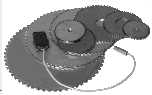 |
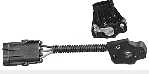
Engine RPM and positionMeasured with a 60 tooth wheel and a magnetic sensor. 120 tooth wheels for camshaft or distributor mounting are optional. Complete drop-in trigger assemblies are also available for some applications. |
 |
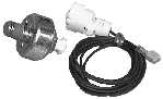
Manifold Absolute Pressure (MAP)Measures vacuum or, on boosted engines, pressure in the intake manifold. |
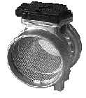 |
Mass Air Flow (MAF)Simplifies the calibration process by measuring the actual mass of the air, in pounds, the engine is drawing in. |
 |
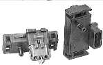
Throttle Position Sensor (TPS)Measures the angle the throttle is open. |
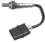 |
Exhaust Gas Oxygen (EGO) SensorMeasures the oxygen content of the exhaust gases allowing the air to fuel ratio of the intake charge to be extrapolated. |
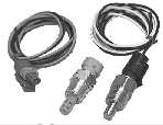 |
Coolant Temperature (CLT) SensorMeasures coolant for enrichments.Manifold Air Temperature (MAT) SensorMeasures intake air for enrichments. |
 |
Knock SensorTEC incorporates programmable, adaptive, knock control. |
- Fuel Injector Firing Patterns
- The TEC offers many advanced features. One example is the availability of different injector firing sequences which may be selected to best suit your particular engine configuration.
- Simultaneous
- All injectors fire at the same time.
- Alternate
- Two batches fire alternately. This is often used with 2 or 4 barrel central Throttle Body Injection (TBI) systems. In a four cylinder, alternate is the same as phased sequential.
- Phased Sequential
- Four pairs of injectors sequencing on 8 cylinders or three pairs sequencing on 6 cylinders - offers benefits of True sequential without the additional hardware: reduced pulsing in the fuel rail, lower emissions, smoother idle and low speed characteristics.
- Idle Air Control (IAC)
- Used on start up as well as for a smooth idle, the TEC is configured to operate a standard GM style idle control motor. By moving a pintle in or out, engine speed is regulated for clean starts and rock steady idle speed. Electromotive stocks several styles of bodies for plumbing the IAC motor into your intake.
- Dual Rev Limiting
- TEC incorporates two types of rev limiters. The soft limiter retards advance to TDC, and the hard limiter which cuts the ignition. An auxiliary limiter may be activated by an external switch and is provided to allow drag racers to burn in their tires. This feature may also be used as a "valet" mode.
- Check Engine Light
- The TEC provides for a dash mounted engine check light. This light is activated in the event of a sensor failure which lasts over half a second and will flash specific failure codes to aid in diagnosis. A limp-home mode is enabled in case of sensor failure.
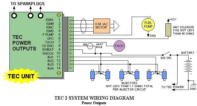
- Fuel Pump Output
- The TEC-II incorporates a ten amp switched output for a fuel pump or other switched circuits. The pump is activated for twenty seconds at key on, and turned off if the engine is then not running.
- Tach Output
- A standard low (0 to 12) volt tach output signal capable of running any modern tachometer is provided. A tach amplifier is available for older tachs that require a higher voltage signal.
- General Purpose Output (GPO)
- The GPO is a pulse width modulated output which may be programmed with a sixty-four position map. It uses the same break point as the ignition advance and V/E tables. It can be used to run any pulse width modulated device, such as a wastegate control solenoid or a nitrous oxide injector. Current output is limited, so a relay must usually be used in these circuits.
- Engine Monitor Screen and Data Logging
- The key to the ease of use of the TEC system is the interactive Engine Monitor Screen, which is included with the calibration software. Just bring it up on your PC or laptop, and engine functions may be monitored and adjusted in real time. Air/fuel ratios are indicated on screen to eliminate the need for expensive additional meters. And with only two numbers to set for the base fuel curve, calibrations are simple to understand and implement. Data logging, with its graphical output, allows the user to record and display run data on a PC.
| Sensor Inputs | Manifold Absolute Pressure | GM 1, 2or 3 bar |
| Throttle Position Sensor | potentiometer, 3 wire | |
| Coolant Temp Sensor | 2.8k ohm @ room temp | |
| Manifold Air Temp | 2.8k ohm @ room temp | |
| Exhaust Oxygen | 1, 3 or 4 wire zirconia | |
| Magnetic Pick-up Sensor (round) | 700 ohm, 60-2 tooth wheel | |
| Magnetic Pick-up Sensor (chisel) | 700 ohm, 120-4 tooth wheel | |
| Knock Sensor | piezoelectric, 6 kHz tuned | |
| Computer Interface | PC serial com port, 3 wire |
| Power Requirements | Battery Voltage | 10 to 16 VDC clean |
| Ground | direct to engine block | |
| Current | 6 to 12 amps dependent on # of Cyl. |
| Outputs | Fuel injector | saturated or peak and hold |
| Fuel injector min resistance | 1.3 ohms combined | |
| Idle Speed Motor | 4 wire 56 ohm stepper motor | |
| Fuel Pump | 10 amps max | |
| GPO coil min resistance | 45 ohms (0.3 amp) | |
| Tachometer output | 0 to 12 V square wave | |
| Check engine bulb | #168 or less (0.3 amp) |
| Performance | Spark output | 120mJ at the sparkplug |
| Spark burn time | 1200 usec | |
| Timing Resolution | (+/-) 1/4 crank degree | |
| RPM range | 60 to 12,000 RPM |